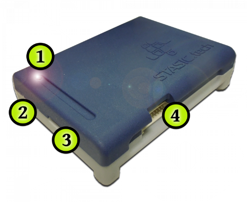
2. RESET button
Tester reset button
3. Power connector
USB 2.0 Type A power connector, cord included.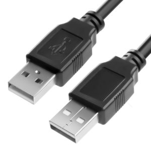
Tester power supply required: DC 5V/2A
This USB connector is additionally used when updating the tester.
4. Hash board connection interface
Hash board connection interface STASIC 20 PIN
1. Switching on the tester
Connect the tester to a DC 5V / 1-2A power source, USB 2.0 Type A cable (supplied),
the tester’s LED indicator will light up and a short beep will sound.
2. connecting to tester via Wi-Fi / updating tester
A) Open WiFi settings, list of wireless networks, on your device (PC/Laptop/Tablet/Smartphone)
B) Select in the list of wireless networks, a network called “Tester123“. Enter WiFi password: stasictester
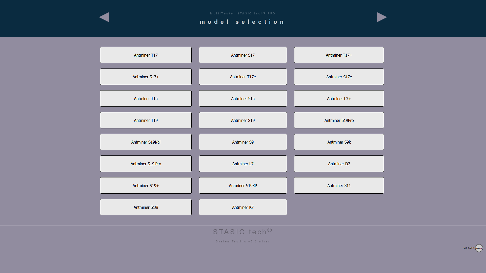
С) Open a browser, type in the address bar: 5.5.5.5/menu – the page for selecting models of supported boards of your version of the tester should appear on the screen.
FAQ If the page is not displayed!?
check if your device (PC/Laptop/Tablet/Smartphone) is connected to the WiFi network of the tester? In the absence of the Internet in the WiFi network of the tester, some devices automatically reconnect to other networks with the presence of the Internet.
- The network addresses of your WiFi adapter can be entered manually, switch to automatically receive from DHCP in the network settings.
- You are trying to use your smartphone as a WiFi adapter to a PC, such a connection scheme will not allow you to work with the tester.
Additional diagnostic modules
Additional diagnostic software module Whatsminer+
ATTENTION! The tester power supply and the hash board power supply must be grounded!
ATTENTION! The hash board must be de-energized before connecting and disconnecting the tester
ALGORITHM FOR CONNECTING HASH BOARD TO TESTER:
- We connect the signal cable of the tester to the hashboard.
- We connect power supply (+\-) to hashboard.
- If tester is powered not from power adapter, but, for example, from a USB computer or other device, then it must be grounded.
- The laboratory power supply (for powering the hashboard) must be grounded.
ALGORITHM FOR DISCONNECTING TESTER FROM HASH BOARD:
- Turn off power to hash board (+\-)
- Disconnect tester signal cable from hashboard.
All of these actions will minimize likelihood of exposure to potential differences and eliminate risk of damage to tester.
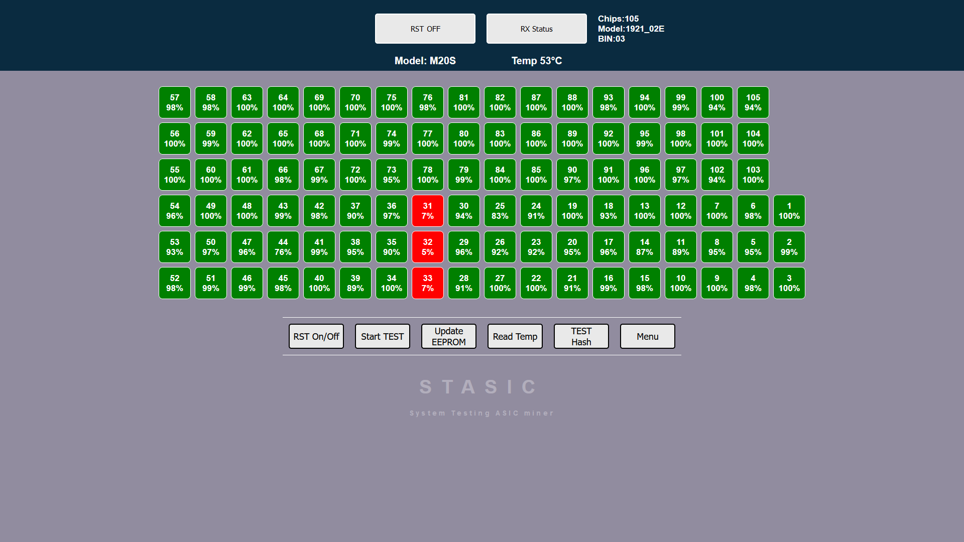
Chip voltage reading function Whatsminer
ATTENTION! for function to work, required power supply for hash board is 12-14 volts, 25 amperes,
A laboratory power supply is being used! PSU ASIC IS NOT SUITABLE!
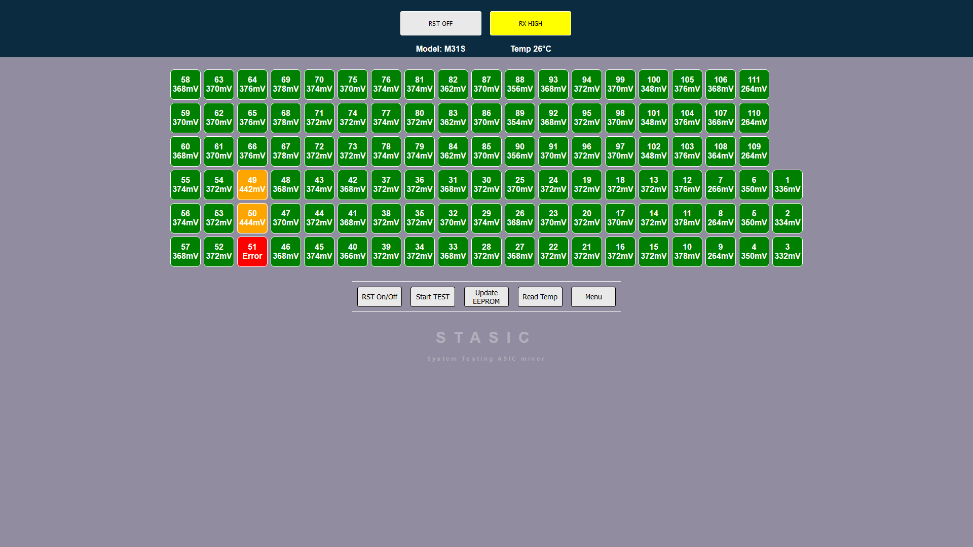
When you press “Read Temp” button for first time, temperature of each chip is polled; when you press it again, information about voltage of each chip is displayed. The function helps diagnose Whatsminer malfunction – “Loss Balance”
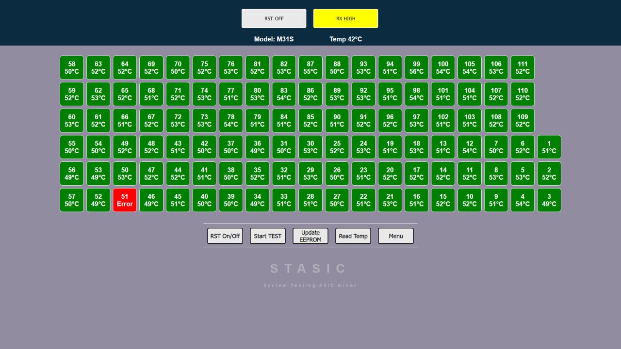
When diagnosing a Loss Balance error, you should pay attention to the voltage readings; on a fully operational board, the voltage readings will be in the same range. If you notice a difference of 90 mV or more, you should pay attention to it. We also conduct tests at different temperatures of the hash board, from room temperature to operating temperature of 60-70 degrees.
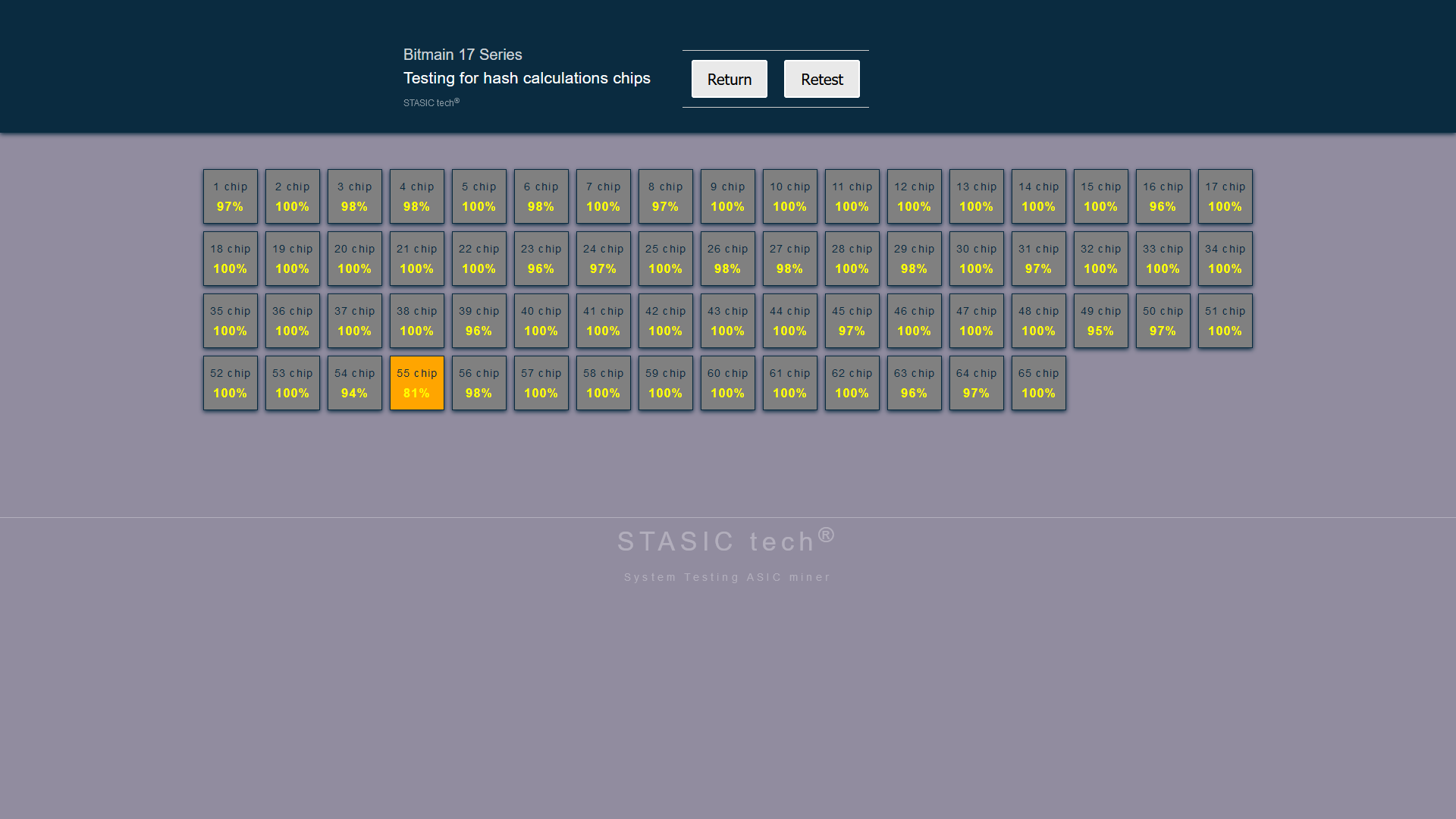
Hash calculation testing function (hash test)
ATTENTION! for function to work, required power supply for hash board is 12-14 volts, 30-75 amperes
(depending on board model and number of chips),
a laboratory power supply is being used!
When performing this test, monitor temperature of hash board, maintain same temperature of hash board each time you press HASH TEST button.
Additional diagnostic software module Antminer+
ATTENTION! The tester power supply and the hash board power supply must be grounded!
ATTENTION! The hash board must be de-energized before connecting and disconnecting the tester
ALGORITHM FOR CONNECTING HASH BOARD TO TESTER:
- We connect the signal cable of the tester to the hashboard.
- We connect power supply (+\-) to hashboard.
- If tester is powered not from power adapter, but, for example, from a USB computer or other device, then it must be grounded.
- The laboratory power supply (for powering the hashboard) must be grounded.
ALGORITHM FOR DISCONNECTING TESTER FROM HASH BOARD:
- Turn off power to hash board (+\-)
- Disconnect tester signal cable from hashboard.
All of these actions will minimize likelihood of exposure to potential differences and eliminate risk of damage to tester.
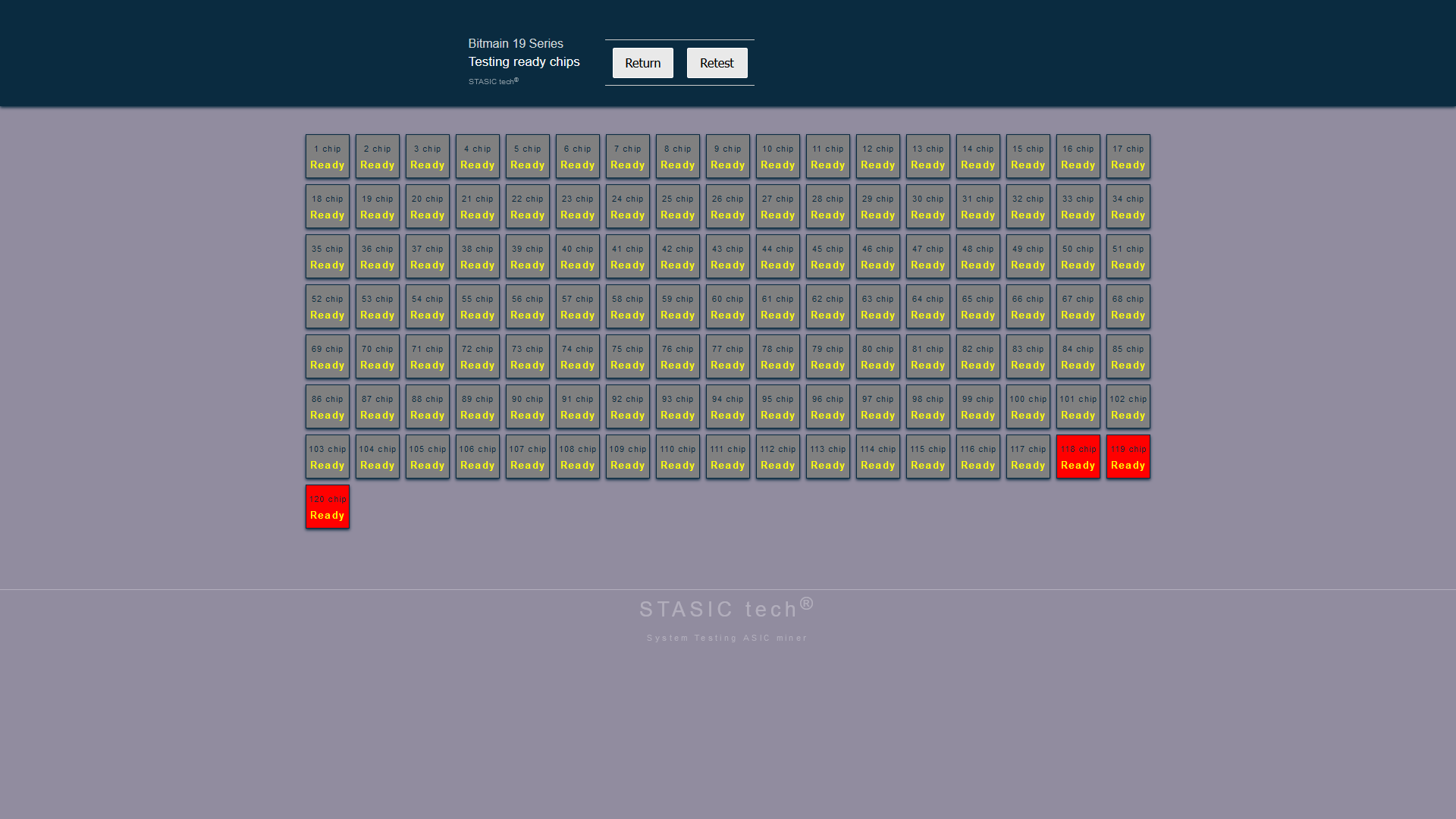
Antminer 17/19 series chip initialization function
ATTENTION! for function to work, a laboratory power supply is being used! PSU ASIC IS NOT SUITABLE!
The initialization function performs a procedure for checking readiness of chip core on hash board, similar to operation of ASIC control board before starting frequency overclocking process and starting mining process. Initialization is carried out on a completely repaired board on which, during a standard test in “START TEST” mode, all green chips are displayed, and temperature sensor readings are also correct. The function is started by pressing “READY CHIP” button
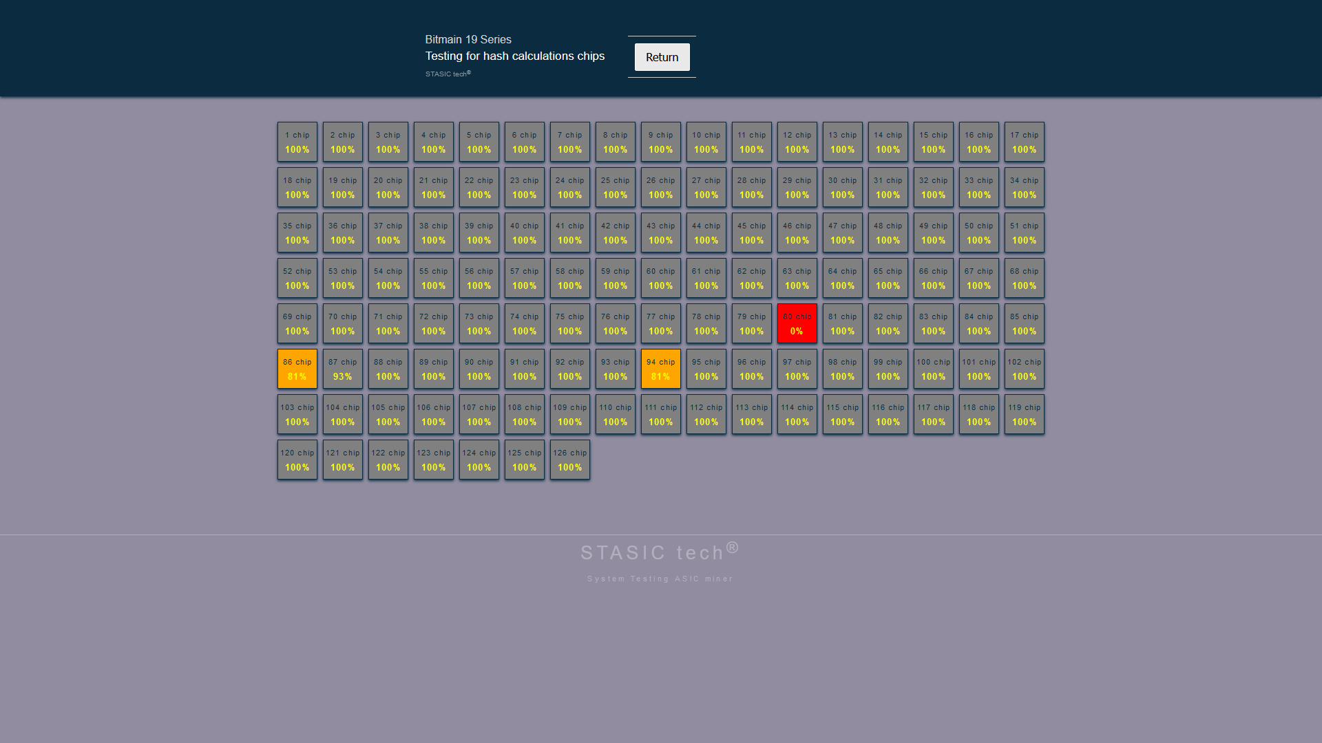
Hash calculation testing function (hash test) Antminer 17/19 series
ATTENTION! required current for the function to operate, 30-65 amperes
(depending on board model and number of chips),
A laboratory power supply is being used! PSU ASIC IS NOT SUITABLE!
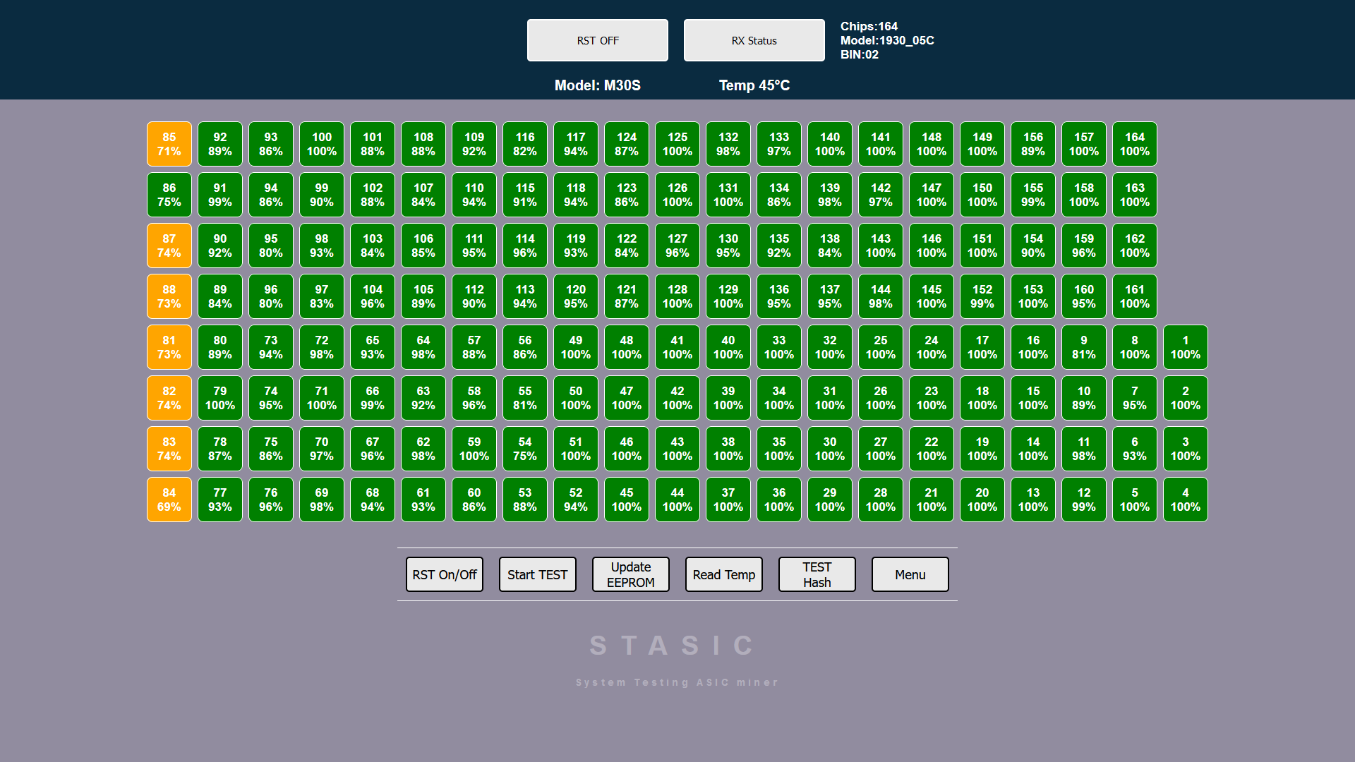
Before performing a hash test, you must select frequency of chips by pressing “OVERCLOCK” button, each press increases frequency. To run one hash calculation test cycle, you need to click “HASH TEST” button.
When conducting this test, monitor temperature of hash board, remember that each time test is run, board consumes from 30 to 65 amps!
Maintain same temperature of hash board every time you press button “HASH TEST”.
If the board is severely overheated, some chips will appear red with a hash value of zero. Do not overheat the hash board by pressing the button frequently “HASH TEST“